ModelingToolkitDesigner.jl
The ModelingToolkitDesigner.jl package is a helper tool for visualizing and editing ModelingToolkit.jl system connections.
Updates
v0.3.0
- Connector nodes are now correctly positioned around the component with natural ordering
v0.2.0
- Settings Files (*.toml) Updates/Breaking Changes
- icon rotation now saved with key
r, previously waswallwhich was not the best name - connectors nodes now saved with an underscore:
_name, this helps prevent a collision with nodes namedx,y, orr
- icon rotation now saved with key
Examples
Examples can be found in the "examples" folder.
Hydraulic Example

Electrical Example

Mechanical Example

Tutorial
Let's start with a simple hydraulic system with no connections defined yet...
using ModelingToolkit
using ModelingToolkitDesigner
using GLMakie

import ModelingToolkitStandardLibrary.Hydraulic.IsothermalCompressible as IC
import ModelingToolkitStandardLibrary.Blocks as B


@parameters t

@component function system(; name)

    pars = []

    systems = @named begin
        stp = B.Step(;height = 10e5, start_time = 0.005)
        src = IC.InputSource(;p_int=0)
        vol = IC.FixedVolume(;p_int=0, vol=10.0)
        res = IC.Pipe(5; p_int=0, area=0.01, length=500.0)
    end

    eqs = Equation[]

    ODESystem(eqs, t, [], pars; name, systems)
end

@named sys = system()
Then we can visualize the system using ODESystemDesign() and the view() functions
path = joinpath(@__DIR__, "design") # folder where visualization info is saved and retrieved
design = ODESystemDesign(sys, path);
ModelingToolkitDesigner.view(design)
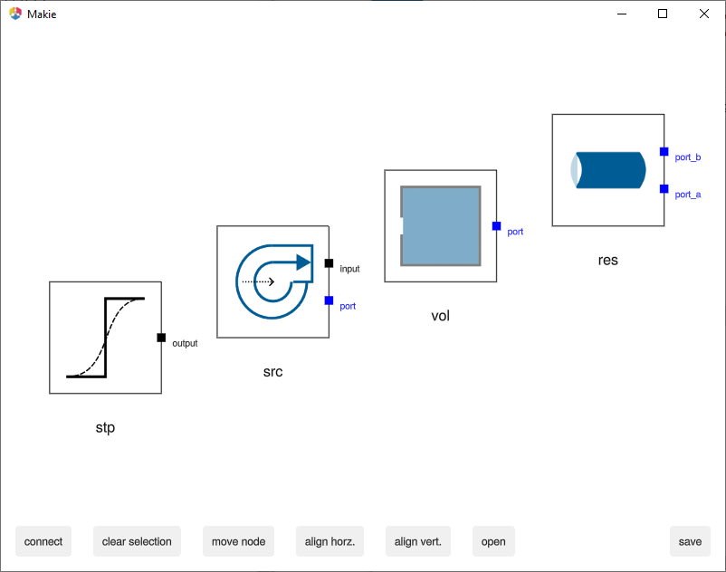
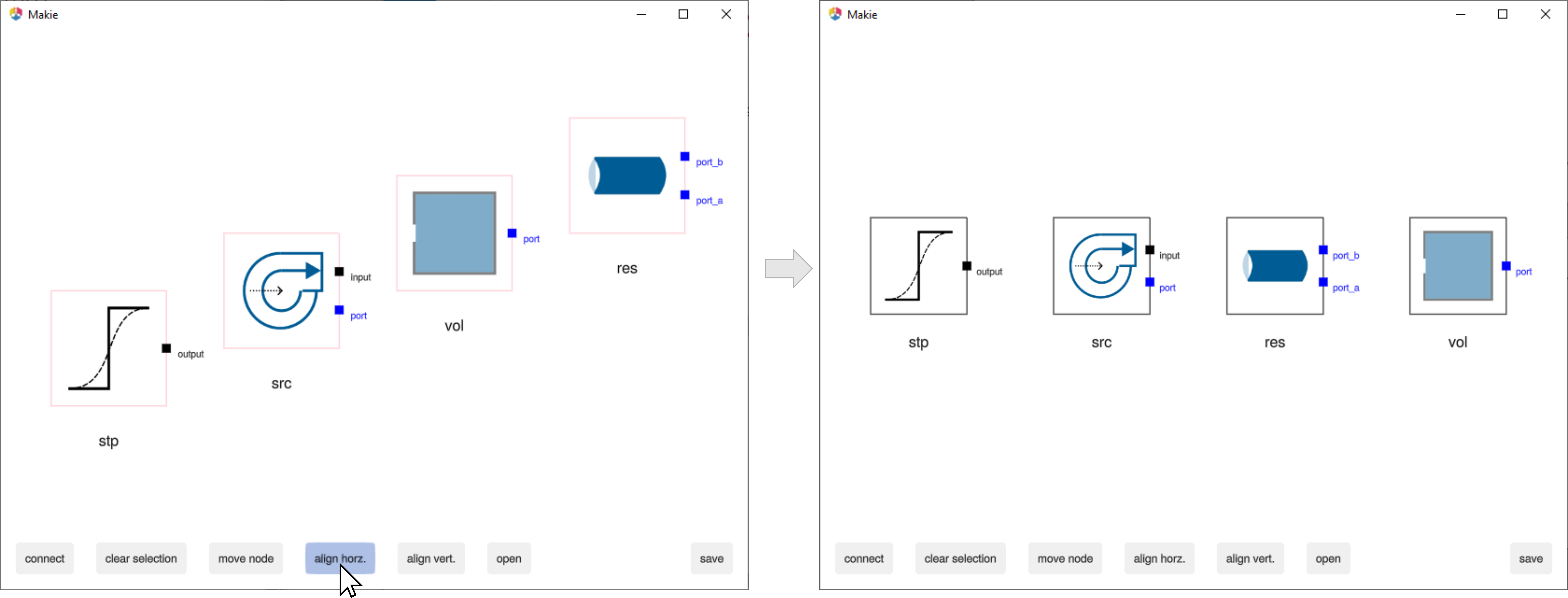
Components can then be positioned in several ways:
- keyboard: select component and then use up, down, left, right keys
- mouse: click and drag (currently only 1 component at a time is supported)
- alignment: select and align horrizontal or vertial with respective buttons
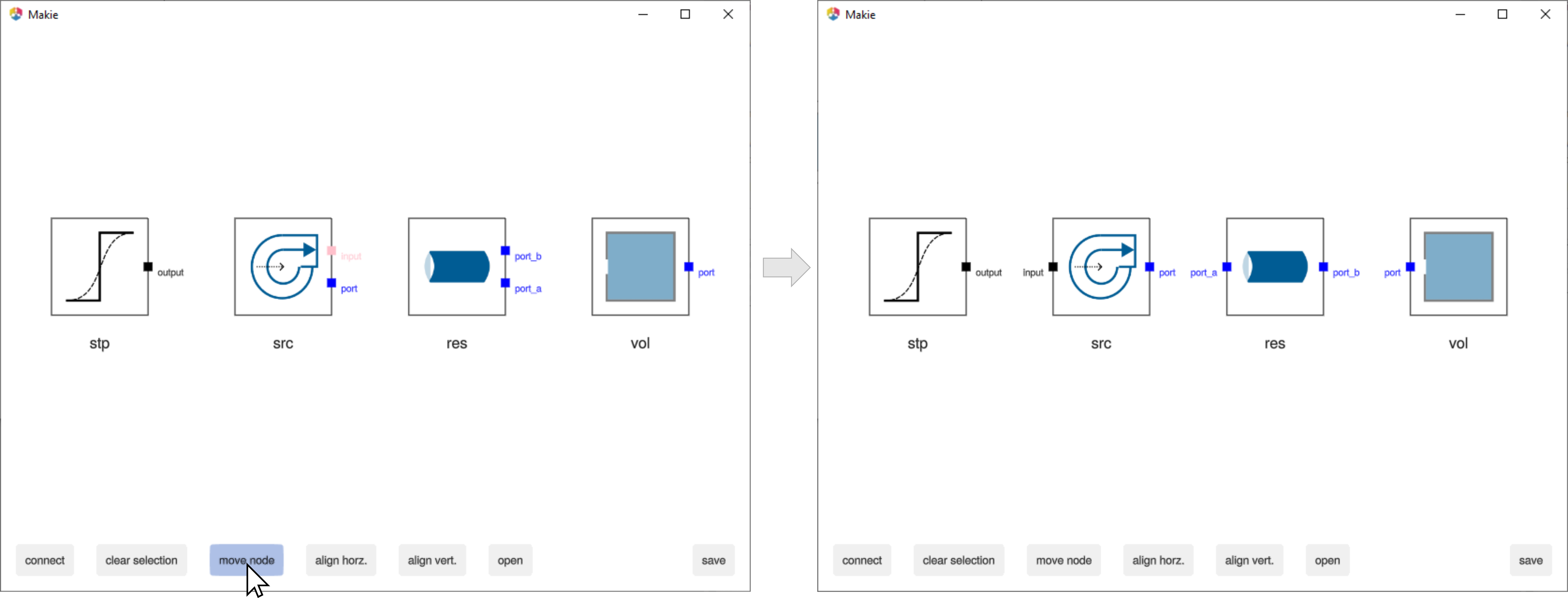
Nodes/Connectors can be positioned by selecting with the mouse and using the move node button. Note: Components and Nodes can be de-selected by right clicking anywhere or using the button clear selection
Connections can then be made by clicking 2 nodes and using the connect button. One can then click the save button which will store the visualization information in the path location in a .toml format as well as the connection code in .jl format.
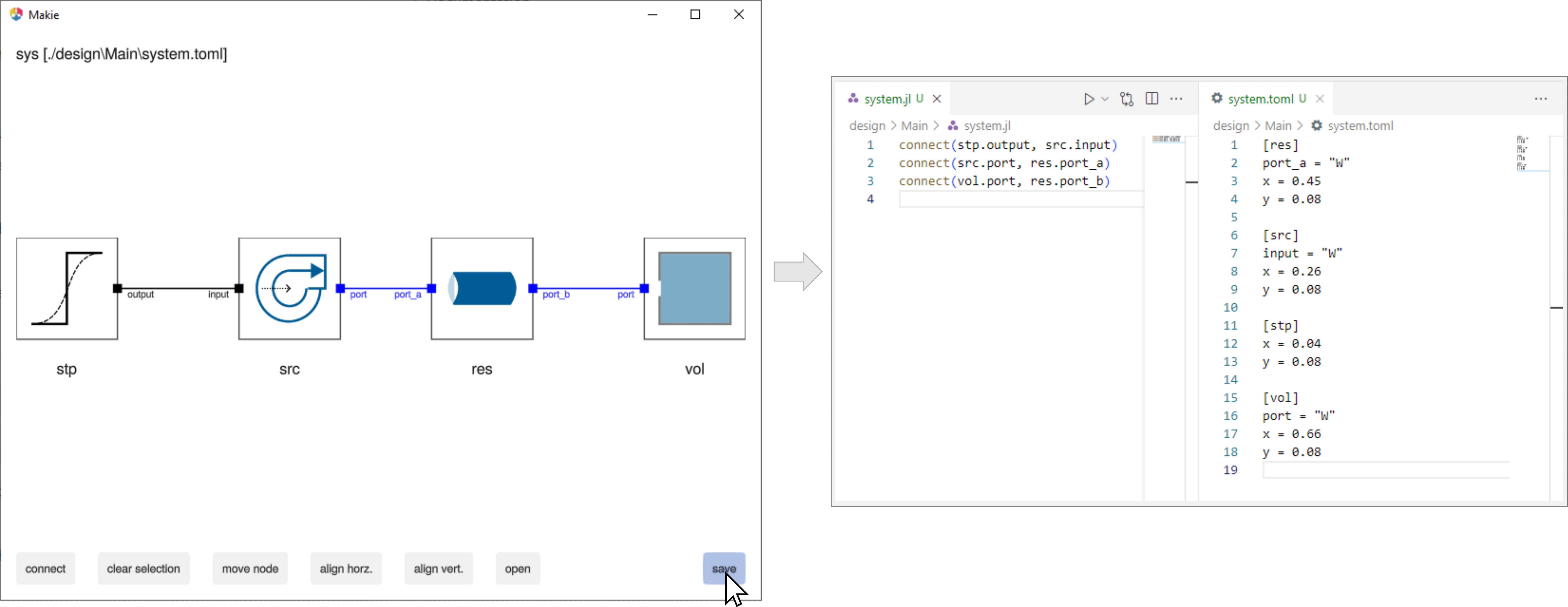
The connection code can also be obtained with the connection_code() function
julia> connection_code(design)
connect(stp.output, src.input)
connect(src.port, res.port_a)
connect(vol.port, res.port_b)
After the original system() component function is updated with the connection equations, the connections will be re-drawn automatically when using ModelingToolkitDesigner.view(). Note: CairoMakie vector based images can also be generated by passing false to the 2nd argument of view() (i.e. the interactive variable).
Hierarchy
If a component has a double lined box then it is possible to "look under the hood". Simply select the component and click open.
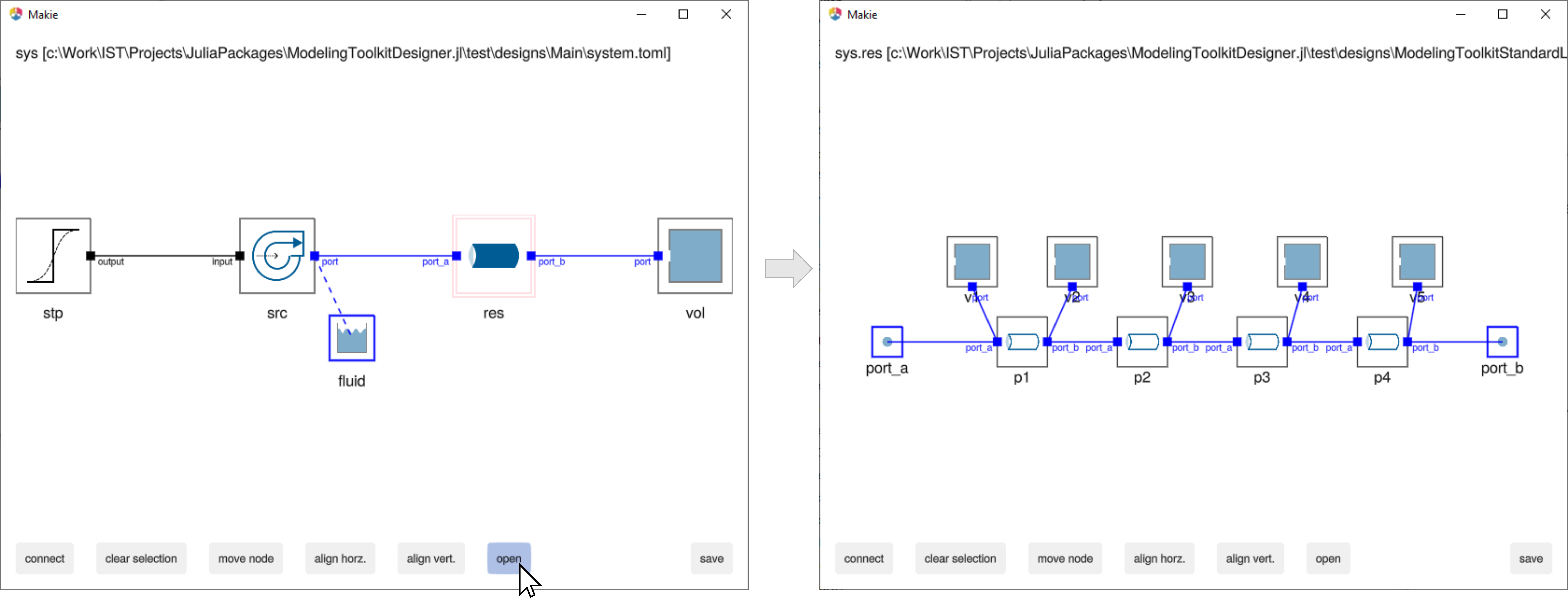
Edits made to sub-components can be saved and loaded directly or indirectly.
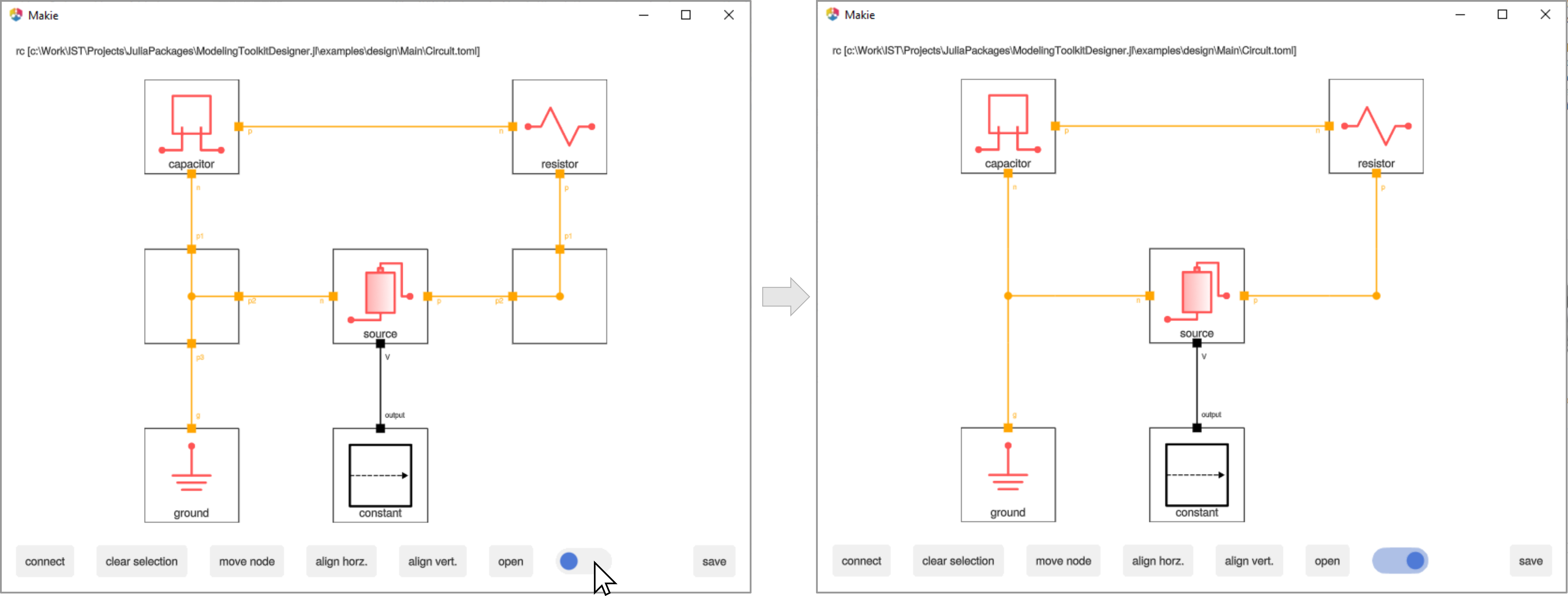
Pass Thrus
To generate more esthetic diagrams, one can use as special kind of component called a PassThru, which simply defines 2 or more connected connectors to serve as a corner, tee, or any other junction. Simply define a component function starting with PassThru and ModelingToolkitDesigner.jl will recognize it as a special component type. For example for a corner with 2 connection points:
@component function PassThru2(;name)
    @variables t

    systems = @named begin
        p1 = Pin()
        p2 = Pin()
    end

    eqs = [
        connect(p1, p2)
    ]

    return ODESystem(eqs, t, [], []; name, systems)
end
And for a tee with 3 connection points
@component function PassThru3(;name)
    @variables t

    systems = @named begin
        p1 = Pin()
        p2 = Pin()
        p3 = Pin()
    end

    eqs = [
        connect(p1, p2, p3)
    ]

    return ODESystem(eqs, t, [], []; name, systems)
end
Adding these components to your system will then allow for corners, tees, etc. to be created. When editing is complete, use the toggle switch to hide the PassThru details, showing a more esthetic connection diagram.
Icons
ModelingToolkitDesigner.jl comes with icons for the ModelingToolkitStandardLibrary.jl pre-loaded. For custom components, icons are loaded from either the path variable supplied to ODESystemDesign() or from an icons folder of the package namespace. To find the paths ModelingToolkitDesign.jl is searching, run the following on the component of interest (for example sys.vol)
julia> println.(ModelingToolkitDesigner.get_icons(sys.vol, path));
...\ModelingToolkitDesigner.jl\examples\design\ModelingToolkitStandardLibrary\Hydraulic\IsothermalCompressible\FixedVolume.png
...\ModelingToolkitStandardLibrary.jl\icons\ModelingToolkitStandardLibrary\Hydraulic\IsothermalCompressible\FixedVolume.png
...\ModelingToolkitDesigner.jl\icons\ModelingToolkitStandardLibrary\Hydraulic\IsothermalCompressible\FixedVolume.png
The first file location comes from the path variable. The second is looking for a folder icons in the component parent package, in this case ModelingToolkitStandardLibrary, and the third path is from the icons folder of this ModelingToolkitDesigner package. The first real file is the chosen icon load path. Feel free to contribute icons here for any other public component libraries.
Icon Rotation
The icon rotation is controlled by the r atribute in the saved .toml design file. Currently this must be edited by hand. The default direction is "E" for east. The image direciton can change to any "N","S","E","W". For example, to rotate the capacitor icon by -90 degrees (i.e. from "E" to "N") simply edit the design file as
[capacitor]
_n = "S"
x = 0.51
y = 0.29
r = "N"
Colors
ModelingToolkitDesigner.jl colors the connections based on ModelingToolkitDesigner.design_colors. Colors for the ModelingToolkitStandardLibrary.jl are already loaded. To add a custom connector color, simply use add_color(system::ODESystem, color::Symbol) where system is a reference to the connector (e.g. sys.vol.port) and color is a named color from Colors.jl.
TODO
- Finish adding icons for the ModelingToolkitStandardLibrary.jl
- Rotate image feature
- Improve text positioning and fontsize
- How to include connection equations automatically, maybe implement the
inputmacro - Provide
PassThru's without requiring user to addPassThrucomponents to ODESystem - Add documentation
[compat]
- ModelingToolkit = "8.50" > needed for Domain feature
- ModelingToolkitStandardLibrary = "1.12" > needed for Hydraulic components